Agenda
- Part 1 – SDF Generation
- Part 2 – SDF Visualisation Methods 👈🏽
- Part 3 – Ambient Occlusion
- Part 4 – Soft Shadows
- Part 5 – SDF Volume Rendering
- Part 6 – Subsurface Scattering
Disclaimer
Night Mode
This post provides a night mode option (bottom-left). This should help some readers which are especially used to dark interfaces. However, as of now, the nightmode also inverts the colors of the images and videos. I apologize about this and I am working on finding a fix.
Introduction
This part will cover implementing various ways for visualising an SDF. We will focus on 2 main techniques to achieve this:
- Visualising an SDF using a cube primitive
- Visualising an SDF using an image effect (a.k.a. camera aligned quad and post-processing)
Visualizing SDFs using a cube
As you recall from our previous part we are generating uniformly sized SDFs. Therefore, we can very easily use a cube as an envelope for an SDF and sphere-march inside it to reveal the object. This a very simple method as it doesn’t require and C# script since it can be done entirely in a shader.
Let’s start by creating a new unlit shader and put it in a Shaders folder so we can stay organized. Next, let’s define the properties of the shader, the subshader and the render pass:
Shader "SDF/SdfVisualiser_Cube"
{
    Properties
    {
        _SDF ("SDF", 3D) = "black" {}
    }
    SubShader
    {
        Tags { "RenderType"="AlphaTest" }
        LOD 100
        Cull Off

        Pass
        {

        }
    }
}
Notice how we are using the “AlphaTest” render type as we will discard the pixels which are not converting any geometry in order to show the background. Next, let’s define some constants and the rest of the usual boilerplate code:
CGPROGRAM
#define MAX_STEP 100
#define EPSILON 0.002
#pragma vertex vert
#pragma fragment frag
// make fog work
#pragma multi_compile_fog

#include "UnityCG.cginc"
Next, let’s define the structure that will provide data to the vertex shader as well as the vertex to fragment structure:
struct appdata
{
    float4 vertex : POSITION;
};

struct v2f
{
    float4 vertex : SV_POSITION;
    UNITY_FOG_COORDS(0)
    float3 worldPos : TEXCOORD1;
    float3 localPos : TEXCOORD2;
};

sampler3D _SDF;
Let’s create the vertex shader next:
v2f vert (appdata v)
{
    v2f o;
    o.vertex = UnityObjectToClipPos(v.vertex);
    o.worldPos = mul(unity_ObjectToWorld, v.vertex).xyz;
    o.localPos = v.vertex.xyz;
    UNITY_TRANSFER_FOG(o, o.vertex);
    return o;
}
The vertex shader is fairly straight-forward. We are computing and assigning the final clip space position, and world space and local space positions which will be used in the fragment shader later on. Before creating the fragment shader we need to create a function that we can use to sample the SDF 3d texture and retrieve the distance:
float SampleSDF(float3 localPos)
{
    // add an offset since Unity's default cube is centered at origin
    localPos += float3(0.5, 0.5, 0.5);
    localPos = clamp(localPos, 0, 1);
    return tex3D(_SDF, localPos).r;
}
Moving on, we arrived at the most important part which is the sphere-marching function:
int SphereMarch(float3 rayOrigin, float3 rayDirection)
{
    float t = 0;
    for (int i = 0; i < MAX_STEP; i++)
    {
        float3 p = rayOrigin + rayDirection * t;
        float d = SampleSDF(p);

        if (d < EPSILON)
        {
            return i;
        }

        t += d;
    }

    return 0;
}
We are iterating for a number of predefined steps, and, at each step, we compute the new local space position, gather the distance and check if the distance is very close to zero. If it is, then we hit the geometry and we return the number of steps required to reach that point. If we didn’t hit anything we continue searching and we use the previously found distance to advance along the ray. If after the predefined number of steps we didn’t hit anything we simply return 0 to indicate this. Now that this function is finished, we can finally implement the fragment shader.
fixed4 frag(v2f i) : SV_Target
{
    float3 direction = normalize(i.worldPos - _WorldSpaceCameraPos.xyz);
    int steps = SphereMarch(i.localPos, direction);

    if (steps == 0)
    {
        discard;
    }

    float c = 1 - ((float)steps / MAX_STEP);
    fixed4 col = fixed4(c, c, c, 1);

    // apply fog
    UNITY_APPLY_FOG(i.fogCoord, col);
    return col;
}
This again is fairly simple. We compute the direction by subtracting the camera position from the current world position of the fragment. Then we run the previously created SphereMarch function and we store the number of steps required to hit something. Remember that if we didn’t hit anything we return 0. Therefore we can check that next and discard the pixel accordingly. Finally, we compute a value in the [0, 1] range indicating the number of steps required to hit a surface. This is better than returning a uniform color as it will help create some definition of the shape.
Now, add a Unity default cube in the scene, create a new material with the shader we just created, and drag and drop it onto the cube. Assign an SDF in the material inspector and we should be able to see the mesh represented by the SDF.
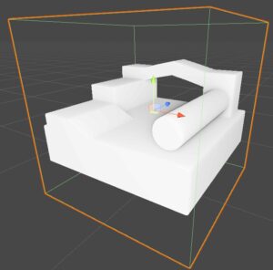
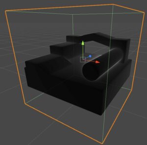
If we remove the 1 - when computing the variable c, we can better visualize where most of the steps are spend, which is when a ray passes very close to a surface without touching it.
And with this, we are done with this method for visualizing SDFs. As you can see it was really simple, however, it suffers from a massive limitation: we cannot go with the camera inside the cube to inspect the SDF up closely because the SDF will disappear. This happens because the fragment where we usually start the sphere-marching is behind the camera and therefore it is discarded so no rendering and implicitly sphere-marching is performed anymore. However, in the next section, we are going to implement the sphere-marching as a post-process effect and we won’t have this limitation anymore.
Don’t forget that if you want to check the full source code of the shader, you check the GitHub repo.
Visualizing SDFs using an image effect
What is an image effect?
I think it’s better to start this section by defining what I mean by an image effect. An image effect or post-processing implies rendering a camera-aligned quad after all the scene rendering is done. Note that the scene is rendered to an off-screen render texture which is then sampled by this quad in order to do some processing on top, such as enhancing colors, depth-based effects (outline, ambient occlusion), bloom, reflections, and a lot more. We are going to use this quad to cast rays in the scene (like in the ray-marching video shown in part 1) and then use a similar sphere-marching algorithm as in the previous section to visualize the mesh represented by our SDF.
Implementing an image effect
Let’s start by writing a C# class that will take care of issuing a draw call for the camera-aligned quad and will also provide the necessary data to the shader used for SDF visualizing. Create a new c# script and name it SdfImageEffect.cs and let’s start by defining some variables, some of them that we can control from the inspector.
using System.Collections;
using System.Collections.Generic;
using UnityEngine;

[ExecuteInEditMode]
[RequireComponent(typeof(Camera))]
public class SdfImageEffect : MonoBehaviour
{
    [SerializeField] private Shader m_sdfVisualiserShader = null;
    [SerializeField] private Texture3D m_sdfTexture = null;

    [SerializeField, Range(0.25f, 10f)] private float m_sdfScale = 1f;
    [SerializeField] private Vector3 m_sdfPosition = Vector3.zero;

    private Material m_imageEffectMaterial = null;
    private Material ImageEffectMaterial
    {
        get
        {
            if (!m_imageEffectMaterial && m_sdfVisualiserShader)
            {
                m_imageEffectMaterial = new Material(m_sdfVisualiserShader);
                m_imageEffectMaterial.hideFlags = HideFlags.HideAndDontSave;
            }
            return m_imageEffectMaterial;
        }
    }

    private Camera m_currentCamera = null;
    private Camera CurrentCamera
    {
        get
        {
            if (!m_currentCamera)
            {
                m_currentCamera = gameObject.GetComponent<Camera>();
            }
            return m_currentCamera;
        }
    }
}
The first thing we are going to add is the OnRenderImage Unity event which is fired after a camera has finished rendering. The event signature contains two parameters, a source, and a destination render texture. We can use the Graphics.Blit method in order to copy the source render texture to the destination using a material.
[ImageEffectOpaque]
private void OnRenderImage(RenderTexture source, RenderTexture destination)
{
    if (!ImageEffectMaterial || !m_sdfTexture)
    {
        // simply replace the source texture with the destination's contents without performing any processing
        Graphics.Blit(source, destination);
    }
    else
    {
        // pass data to the shader
        ImageEffectMaterial.SetTexture("_SDF", m_sdfTexture);
        ImageEffectMaterial.SetMatrix("_SDFMappingMatrix", GetVolumeMappingFunction());
        ImageEffectMaterial.SetMatrix("_FrustumCornersMatrix", GetFrustumCorners());
        ImageEffectMaterial.SetFloat("_SdfScale", m_sdfScale);
        ImageEffectMaterial.SetVector("_SdfPosition", m_sdfPosition);
        ImageEffectMaterial.SetMatrix("_CameraInvViewMatrix", CurrentCamera.cameraToWorldMatrix);

        // copy the source texture into the destination using a provided material
        // the shader attached to this material will perform the sphere-marching algorithm
        Graphics.Blit(source, destination, ImageEffectMaterial, 0);
    }
}
As you can see, if there is no shader nor an SDF 3D texture provided in the inspector we will perform a simple swap of the textures. However, if the required data is provided we are setting up a bunch of variables in the material, and then, calling the same Blit function, this time however providing a material that will be used in the copying process. The last parameter in the Blit function indicates which pass of the material should be used, which in our case is the first one (0).
Most of the data set to the shader should make sense (e.g. _SDF is the 3D texture that stores the SDF), however, some of them might seem strange at first. For instance _SDFMappingMatrix is used to convert a world space position to the local space of the 3D texture (in [0, 1] range) so we can sample it. It is basically a matrix composed of the inverse of the _SdfPosition and the inverse of the _SdfScale. It is computed as follows:
private Matrix4x4 GetVolumeMappingFunction()
{
    Matrix4x4 scale = Matrix4x4.Scale(Vector3.one * (1f / m_sdfScale));
    Matrix4x4 translate = Matrix4x4.Translate(-m_sdfPosition + Vector3.one * (m_sdfScale / 2f));
    return scale * translate;
}
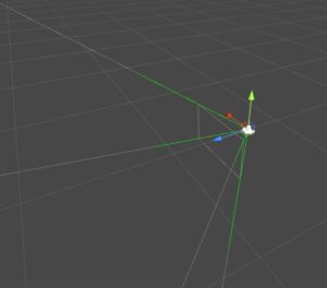
The _FrustumCornersMatrix is probably the most interesting one. As I explained before we are going to render a camera-aligned quad where for each pixel we are going to cast a ray in the scene, but we will need a ray direction in order to do this. An easy way to do this is to precompute a ray for each of the 4 corners of the camera-aligned quad and pass it to the shader. Since we are going to send 4 vectors we can pack them into a Matrix (4×4) for convenience. Then we will let the GPU interpolate those corner vectors so we can have a direction for every pixel. This is exactly what the method GetFrustumCorners is doing:
private Matrix4x4 GetFrustumCorners()
{
    float camFov = CurrentCamera.fieldOfView;
    float camAspect = CurrentCamera.aspect;

    Matrix4x4 frustumCorners = Matrix4x4.identity;

    float halfFov = camFov * 0.5f;
    float tanFov = Mathf.Tan(halfFov * Mathf.Deg2Rad);

    Vector3 toRight = Vector3.right * tanFov * camAspect;
    Vector3 toTop = Vector3.up * tanFov;

    Vector3 bottomLeft = Vector3.Normalize(-Vector3.forward - toRight - toTop);
    Vector3 topLeft = Vector3.Normalize(-Vector3.forward - toRight + toTop);
    Vector3 topRight = Vector3.Normalize(-Vector3.forward + toRight + toTop);
    Vector3 bottomRight = Vector3.Normalize(-Vector3.forward + toRight - toTop);

    frustumCorners.SetRow(0, bottomLeft);
    frustumCorners.SetRow(1, topLeft);
    frustumCorners.SetRow(2, topRight);
    frustumCorners.SetRow(3, bottomRight);

    return frustumCorners;
}
You can see in the image below how the frustum corners vectors look like.
The image effect shader
Let’s create a new unlit shader that will be used with our Blit material. We can place it in the Hidden category as we will assign it to the inspector.
Shader "Hidden/SDFVisualiser_ImageEffect_Simple"
{
    Properties
    {
        _MainTex("Main Tex", 2D) = "black" {}
    }
    SubShader
    {
        Cull Off ZWrite Off ZTest Always

        Pass
        {
           CGPROGRAM
           #pragma vertex vert
           #pragma fragment frag
           #include "UnityCG.cginc"

           #define MAX_STEP 128
           #define EPSILON 0.002
        }
    }
}
Next, let’s declare all the variables that we are sending from the SdfImageEffect.cs:
uniform sampler2D _MainTex;
uniform float4 _MainTex_TexelSize;
uniform float4x4 _FrustumCornersMatrix;
uniform float4x4 _CameraInvViewMatrix;

uniform sampler3D _SDF;
uniform float4x4 _SDFMappingMatrix;
uniform float _SdfScale;
uniform float3 _SdfPosition;
And now some structs:
struct appdata
{
    float4 vertex : POSITION;
    float2 uv : TEXCOORD0;
    uint id : SV_VertexID;
};

struct v2f
{
    float2 uv : TEXCOORD0;
    float4 vertex : SV_POSITION;
    float3 ray : TEXCOORD1;
};

struct Ray
{
    float3 Origin;
    float3 Direction;
};
We are going to use the SV_VertexID to acquire the unsigned integer ID of every vertex so we can access the matching row of the _FrustumCornersMatrix which contains the precomputed ray direction. Among other common things this is implemented in the vertex shader as follows:
v2f vert(appdata v)
{
    v2f o;
    o.vertex = UnityObjectToClipPos(float4(v.vertex.xy, 0, 1));
    o.uv = v.uv;
    #if UNITY_UV_STARTS_AT_TOP
    if (_MainTex_TexelSize.y < 0)
        o.uv.y = 1 - o.uv.y;
    #endif
    o.ray = _FrustumCornersMatrix[v.id].xyz;
    o.ray = mul(_CameraInvViewMatrix, o.ray); // transform the direction from view space to world space
    return o;
}
Next, let’s implement an SDF sampling function similar to the one we implemented in the previous section, this one, however, will be slightly complex as we are providing a world space position and we want to it convert to texture-space (remember the [0, 1] range).
float SampleSDF(float3 wsPosition)
{
    wsPosition = mul(_SDFMappingMatrix, float4(wsPosition, 1)).xyz;
    wsPosition = clamp(wsPosition, 0, 1);
    return tex3D(_SDF, wsPosition).r * _SdfScale;
}
Note how we multiple our normalized distance by _SdfScale in order to account for the scale that we want to visualize the SDF at.
The next function we are going to implement will help us optimize a bit the algorithm. As you know for every pixel we have to cast a ray into the scene and sphere-march it, while sampling the SDF and checking the distance at every step. Consider for a moment that we have the SDF at the center of the camera view, then most of the rays close to the edges of the view will be wasted as they will never hit the SDF. Therefore, in order to save those wasted steps, we are going to perform a ray to AABB (axis-aligned bounding box) collision check. Only if the collision check passes we are going to do the sphere-marching. Regarding the ray to AABB intersection Majercik et al. provides a good overview of existing algorithms and also presents an own implementation which is extremely performant as it only has 9 lines of code and doesn’t require any for–loops.
bool RayToAabb(float3 aabbMin, float3 aabbMax, Ray ray, out float tHit, float tMinLimit, float tMaxLimit)
{
    float3 invRayDir = rcp(ray.Direction);
    float3 t0 = (aabbMin - ray.Origin) * invRayDir;
    float3 t1 = (aabbMax - ray.Origin) * invRayDir;

    float3 tMinVec = min(t0, t1);
    float3 tMaxVec = max(t0, t1);

    float tMin = max(tMinLimit, max(tMinVec[0], max(tMinVec[1], tMinVec[2])));
    float tMax = min(tMaxLimit, min(tMaxVec[0], min(tMaxVec[1], tMaxVec[2])));

    tHit = tMin;
    return (tMin < tMax);
}
In the RayToAabb function tMinLimit and tMaxLimit are used as limits for the distance from the origin along the direction in which we want to check for the collision. The tHit variable will output the distance from the origin (along the direction) where the collision occurs.
The sphere-marching algorithm is similar to the one we wrote in the shader from the previous section:
int SphereMarch(Ray ray)
{
    float t = 0;
    for (int i = 0; i < MAX_STEP; i++)
    {
        float3 p = ray.Origin + ray.Direction * t;
        float d = SampleSDF(p);

        if (d < EPSILON)
        {
            return i;
        }

        t += d;
    }

    return i;
}
And we finally, reached the last function of the shader which is the fragment one. Here we basically do some quick calculation for the AABB corners of the early ray-AABB collision check and then based on the early collision test we run the sphere marching algorithm or simply return the existing color.
fixed4 frag(v2f i) : SV_Target
{
    // the final color
    fixed3 col = fixed3(0, 0, 0);

    Ray ray;
    ray.Origin = _WorldSpaceCameraPos.xyz;
    ray.Direction = normalize(i.ray);

    float3 aabbMin = _SdfPosition - (_SdfScale.xxx / 2);
    float3 aabbMax = _SdfPosition + (_SdfScale.xxx / 2);

    float t = 0;
    int steps = 0;
    if (RayToAabb(aabbMin, aabbMax, ray, t, 0.001, 100))
    {
        // advance the ray origin to the box intersection
        ray.Origin += ray.Direction* t;
        steps = SphereMarch(ray);
        float c = 1 - ((float)steps / MAX_STEP);
        col = fixed4(c, c, c, 1);
     }
     else
     {
        col = tex2D(_MainTex, i.uv);
     }

     return fixed4(col, 1);
}
Notice how this is pretty similar to the shader we did in the previous section with just a few additions.
You can also check the GitHub repo here. It also contains a camera controller script and some and some other additions.
One Comment