Agenda
- Part 1 – SDF Generation 👈🏽
- Part 2 – SDF Visualisation Methods
- Part 3 – Ambient Occlusion
- Part 4 – Soft Shadows
- Part 5 – SDF Volume Rendering
- Part 6 – Subsurface Scattering
Disclaimer
Night Mode
This post provides a night mode option (bottom-left). This should help some readers which are especially used to dark interfaces. However, as of now, the nightmode also inverts the colors of the images and videos. I apologize about this and I am working on finding a fix.
Difficulty Level
This is not a beginner-friendly tutorial. Most of the techniques and concepts presented and introduced in this series require some basic understanding of Unity engine, shaders, and shader programming as well as some basic algebra and geometry. This series will not provide an introduction to Unity shader programming as there are already quite a lot of great resources on this topic on the internet. To mention a few:
- catlikecoding rendering series provides not only a very good introduction to shaders but also to how Unity’s built-in rendering pipeline works. I also recommend this one which covers compute shaders.
- Harry Alisavakis has an amazing series for everyone who is just starting out in shader or graphics programming. It offers not only a strong introduction to shaders but also various computer graphics fundamental concepts regarding the components of a 3D object and how they are stored and provided to shaders. He is also the author of a weekly collection of tweets regarding technical art which is also worth checking out.
- Ronja’s basic shader tutorials are great for everyone who is new at writing shaders. Additionally, the compute shader series is also very useful for beginners on this topic.
- A gentle introduction to shaders by Alan Zucconi is extremely well written and presented;
Unity Version & Rendering Pipeline
This series will be using Unity 2020.2.2f1 and the built-in rendering pipeline. Maybe in one of the following parts of the series, I will cover URP as well.
Introduction
What is a Signed Distance Field?
A Signed Distance Field (SDF) represents an alternative method for describing and storing environment data. They are not meant to replace traditional methods for authoring, storing, and displaying scene geometry. SDFs act as an extension used to improve various fields of real-time rendering or to achieve some specific effects. Their major advantage is the uniform distribution of the scalars representing the distances to nearby geometry, which allows for very fast environmental queries.
But why do we need fast environment queries in the first place? As you know shaders are provided with very little or no data about the surrounding geometry. The lack of availability of spatial data in shaders is one of the main limitations of the real-time renders and SDFs offer a solution for this. For example, when a mesh is uploaded to the GPU for rendering, the vertex shader cannot access the other vertice’s position by default. Additionally, in the pixel shader, certain effects have to rely on the depth buffer in order to understand how the environment looks and perform the shading accordingly. Imagine a water shader, which should detect whenever a mesh is interesting the water plane in order to color it white to represent some foam accumulated near the intersection. Without providing any additional data to the shader the fastest way to achieve this is to inspect the depth buffer in order to compare the current position with any nearby ones. There are many more situations in which rendering engines need to rely on different tricks to describe the surrounding geometry in order to achieve global effects. (shadows and shadow-mapping, reflections and reflection probes, etc.).
In the same way, a shadow map is used to describe the distance to a light source in order to understand which pixels are shadowed, an SDF is used to describe the geometry in a ray marching friendly format. The next section will dive into the raymarching algorithm and it will show why exactly an SDF is so useful when doing raymarching. In the meantime let’s see how an SDF is structured.
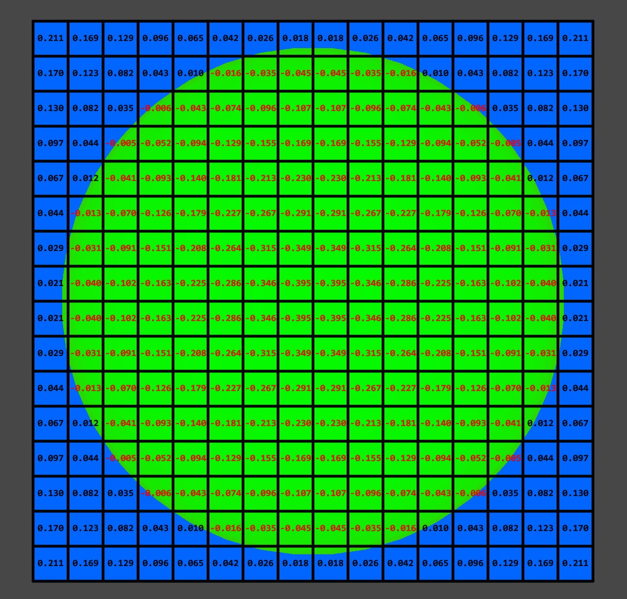
While the introduction to SDFs might seem complicated, they are actually very simple. An SDF is a 3D grid-like structure that encapsulates a mesh, and every cell/voxel in the grid contains the distance to the closest point of the encapsulated mesh. Since a distance is always positive you might wonder why they have signed in their name. This is for the very simple reason that we want to store 2 pieces of information in each voxel. One is the distance and the other one is whether or not the voxel is inside or outside the mesh. In order to indicate this, we can simply put a minus in front of the distances that are for the voxels contained inside the mesh. With this approach with a single number, we can know 2 things: the distance to the mesh and if the voxel is inside or outside.


Ray Marching
Ray marching is a variant of ray tracing designed to be implemented in the fragment shader in a real-time renderer. The main difference compared with traditional ray casting is that it removes the ray-geometry equations which are computationally expensive. Instead, it uses a step, in order to march through the scene, and at each step, it is checking if it hits an object. Even if is not as precise as traditional ray equations the performance is greatly improved.
Again, Alan Zucconi has a great article going in-depth about this topic. I will give a super quick explanation about the algorithm. Ray marching is executed in the pixel shader. It can be done in a camera aligned quad (like for post-processing) or on a regular piece of geometry (e.g. a cube). For every fragment, (every fragment/pixel shader invocation) the shader will start from the fragment’s world position and will move along a ray which pointing from the camera towards the scene. The movement is an iterative process and the distance moved each iteration/step can be either constant or variable. At each step, the algorithm evaluates a distance function or an SDF in order to determine whether we have a collision or not. If there is a collision, we can shade that pixel accordingly. The algorithm terminates after a fixed number of steps when we can safely assume that the ray didn’t hit anything and we can return something like a sky color.
They say a video is worth 1000 words. I believe it can be worth much more than when it comes to explaining certain concepts, raymarching being one of them. Therefore, please take a look at the video below to check an animation I made that illustrates how raymarching works.
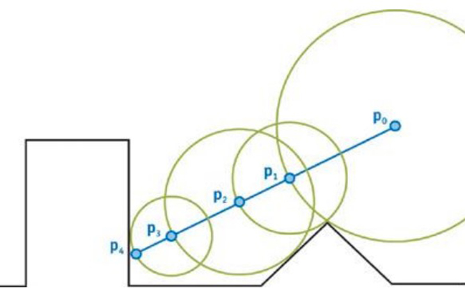
The step size and the maximum number of steps have the highest influence on the performance of the algorithm. In most of the scenarios having a constant step, size is a huge waste of resources. Take a look at the picture below and note how many steps we are wasting because, for each one of them, we have to check the distance to the sphere. Keep in mind that at each point we have either a signed distance function or an SDF that can tell us what is the distance to the closest surface. Therefore, we could just start from the camera aligned quad, get the distance to the sphere and move directly to the surface of the sphere in one, single step.
A lot of wasted steps.
Enter sphere marching, a version of raymarching on steroids that includes the concept I presented above, which is using a variable step size in order to improve the performance and efficiency of the algorithm. The step size is therefore determined by the closest distance to any geometry in the world. Consequently, the ray can safely advance without hitting anything while also removing unnecessary iteration steps in empty areas that would otherwise be computed when using a constant step size.
Sphere marching using closest distance as the step size.
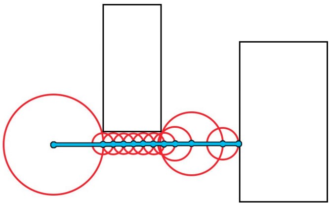
When using sphere tracing the ray march step is smaller when a ray is closer to a surface even if the ray might not hit that surface.
Generating SDFs
Now that the introduction was laid out, the next part is to focus on actually generating an SDF. The next section will take care of creating a Unity editor window where we can drag and drop a mesh which can be then processed and the resulting SDF will be stored into a 3D texture. I will try to keep this section as short as possible and only present the important details. If you are new to scripting, compute shaders, or Unity in general I highly recommend getting used to the basics first.
Setting Up The Project
To start with, create a Unity 2020.2.2f project using the built-in pipeline. Then create a new script and inherit it from EditorWindow class. We are going to implement the SDF generator user interface into a Unity editor window, in which we can drag and drop a mesh, select the SDF resolution and then click Bake in order to generate the SDF and store it in a 3d texture. The script for the Editor window is fairly simple:
using System;
using System.Collections;
using System.Collections.Generic;
using System.IO;
using UnityEditor;
using UnityEngine;

public enum PowerOf8Size
{
    _16 = 16,
    _32 = 32,
    _64 = 64,
    _96 = 96,
    _128 = 128,
    _160 = 160,
    _200 = 200,
    _256 = 256
};

public class SdfGeneratorWindow : EditorWindow
{
    private string m_savePath
    {
        get => EditorPrefs.GetString("SdfGenerator_SavePath", string.Empty);
        set => EditorPrefs.SetString("SdfGenerator_SavePath", value);
    }
    private int m_sdfResolution = 32;
    private Mesh m_mesh;


    [MenuItem("Utilities/SDF Generator")]
    static void Init()
    {
        SdfGeneratorWindow window = (SdfGeneratorWindow)EditorWindow.GetWindow(typeof(SdfGeneratorWindow));
        window.Show();
    }

    public void OnGUI()
    {
        GUILayout.BeginVertical();

        // title
        EditorGUILayout.Space();
        GUILayout.Label("--- SDF Generator ---", new GUIStyle(EditorStyles.centeredGreyMiniLabel)
        {
            fontSize = 12,
            alignment = TextAnchor.MiddleCenter
        });
        EditorGUILayout.Space();

        // save location for the SDF
        GUILayout.BeginHorizontal();
        {
            GUI.enabled = false;
            EditorGUILayout.TextField("Save Location", m_savePath, GUILayout.MaxWidth(600));
            GUI.enabled = true;

            if (GUILayout.Button(EditorGUIUtility.IconContent("d_Folder Icon"), GUILayout.MaxWidth(40), GUILayout.MaxHeight(EditorGUIUtility.singleLineHeight)))
            {
                m_savePath = EditorUtility.SaveFolderPanel("SDF Save Location", m_savePath, "").Substring(Application.dataPath.Length).Insert(0, "Assets");
            }
        }
        GUILayout.EndHorizontal();

        // resolution of the sdf
        m_sdfResolution = Convert.ToInt32((PowerOf8Size)EditorGUILayout.EnumPopup("SDF Resolution", (PowerOf8Size)m_sdfResolution));

        // the mesh to compute the SDF from
        m_mesh = EditorGUILayout.ObjectField(new GUIContent("Mesh"), m_mesh, typeof(Mesh), false) as Mesh;

        EditorGUILayout.Space();

        // show the button as not interactable if there is no mesh assigned
        GUI.enabled = (m_mesh != null);

        // use horizontal layout and flexible space to center the button horizontally
        EditorGUILayout.BeginHorizontal();
        GUILayout.FlexibleSpace();
        if(GUILayout.Button("Generate SDF", GUILayout.MaxWidth(150f)))
        {
            // TODO: call the SDF generator function
        }
        GUI.enabled = true;
        GUILayout.FlexibleSpace();
        EditorGUILayout.EndHorizontal();

        GUILayout.EndVertical();
    }

    private void Save3DTexture(Texture3D texture)
    {
        string path = Path.Combine(m_savePath, $"{m_mesh.name}_SDF_{m_sdfResolution}.asset");
        AssetDatabase.CreateAsset(texture, path);
        AssetDatabase.SaveAssets();
        AssetDatabase.Refresh();
    }
}
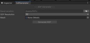
Notice how on line 82 I left the functionality of the button empty. Now save the script, wait for it to compile and now we can open the window from Utilities>SDF Generator.
Now comes the important part, writing the actual SDF generator logic, which will take care of setting up and dispatching the compute shader and retrieving data from the GPU ready to be stored in a 3D texture. Create a new script and give it the name SdfGenerator.cs. We don’t need to inherit from MonoBehaviour, this will be a static class that we can call from our editor window or even at runtime if we want.
using System.Runtime.InteropServices;
using System.Text;
using UnityEngine;

public static class SdfGenerator
{
}
We are going to store the SDF in a one dimensional compute buffer when it is processed by the compute shader. Initially, I used a 3D render texture, however they are pretty complicated to convert to a regular 3D texture. With a compute buffer we can do the conversion using a bunch of nested for loops. Therefore let’s first create a method that will return a compute buffer from a given SDF resolution.
private static ComputeBuffer GetOutputBuffer(int sdfResolution)
{
    int cubicSdfResolution = sdfResolution * sdfResolution * sdfResolution;
    ComputeBuffer outputBuffer = new ComputeBuffer(cubicSdfResolution, Marshal.SizeOf(typeof(float)));
    return outputBuffer;
}
Next, we need to create some similar methods that will convert the mesh data to a compute buffer, suitable to be uploaded to the GPU. The mesh data we need consists of vertices, triangles, and normals. Therefore we need three different methods which look like this:
private static ComputeBuffer GetMeshNormalsBuffer(Mesh mesh)
{
    ComputeBuffer outputBuffer = new ComputeBuffer(mesh.normals.Length, Marshal.SizeOf(typeof(Vector3)));
    outputBuffer.SetData(mesh.normals);
    return outputBuffer;
}

private static ComputeBuffer GetMeshVerticesBuffer(Mesh mesh)
{
    ComputeBuffer outputBuffer = new ComputeBuffer(mesh.vertices.Length, Marshal.SizeOf(typeof(Vector3)));
    outputBuffer.SetData(mesh.vertices);
    return outputBuffer;
}

private static ComputeBuffer GetMeshTrianglesBuffer(Mesh mesh)
{
    ComputeBuffer outputBuffer = new ComputeBuffer(mesh.triangles.Length, Marshal.SizeOf(typeof(int)));
    outputBuffer.SetData(mesh.triangles);
    return outputBuffer;
}
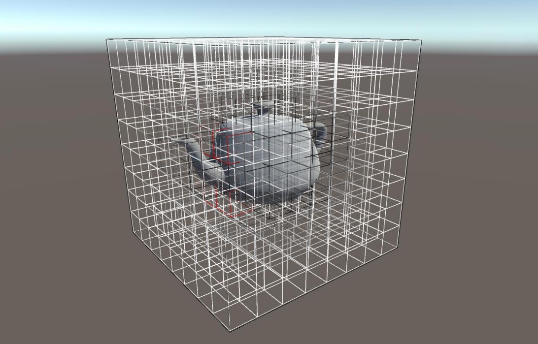
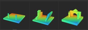
Next, we need to take care of doing some optimization regarding the world space scale of the SDF. Think about our SDF as a cube positioned in world space. This cube is internally subdivided based on a predefined resolution. Now, ideally, we want this cube to encapsulate our mesh as close as possible, in order to waste as little as possible voxels on unoccupied areas.
Fortunately, Unity already computes an axis-aligned bounding box for every imported mesh. In the previous image, it is shown in white. You can see that it perfectly encapsulates the mesh. This, however, is not ideal in our current implementation because we only support uniformly scaled SDF, which are volumes with the same resolution in each of the 3 dimensions (e.g. 32 x 32 x 32). Therefore we need to implement some methods to transform the bounding box provided by Unity (in white in the previous image) into the blue one.
private static Vector3 ComputeMinExtents(Bounds meshBounds)
{
    float largestSide = MaxComponent(meshBounds.size);
    float padding = largestSide / 20;
    return meshBounds.center - (Vector3.one * (largestSide * 0.5f + padding));
}

private static Vector3 ComputeMaxExtents(Bounds meshBounds)
{
    float largestSide = MaxComponent(meshBounds.size);
    float padding = largestSide / 20;
    return meshBounds.center + (Vector3.one * (largestSide * 0.5f + padding));
}

private static float MaxComponent(Vector3 vector)
{
    return Mathf.Max(vector.x, vector.y, vector.z);
}
We are almost done, however, we have one extra step left to do before we start writing the actual SDF generation method. As I mentioned earlier we are going to store our SDF in a 3D texture. This has several benefits, such as being able to easily save it as a .asset file inside the project, and we can reference it for runtime usage, or even transfer it between projects. The second advantage is that, since Unity 2020, we can visualize the SDF right in the inspector preview, this is a huge timesaver and quality of live improvement. However, if you recall from the first method that we created for our SdfGenerator class, our compute shader will store the result in a linear, one-dimensional ComputeBuffer class. Therefore we need to convert it to a 3D texture. This is quite simple in practice, and although there might be other possible techniques to accomplish this, I found the next one to be the easiest and the most convenient one:
private static Texture3D Texture3dFromData(float[] outputData, int sdfResolution)
{
    Texture3D tex3D = new Texture3D(sdfResolution, sdfResolution, sdfResolution, TextureFormat.RFloat, false);
    tex3D.anisoLevel = 1;
    tex3D.filterMode = FilterMode.Bilinear;
    tex3D.wrapMode = TextureWrapMode.Clamp;

    Color[] colors = tex3D.GetPixels();
    for (int y = 0; y < sdfResolution; y++)
    {
        for (int z = 0; z < sdfResolution; z++)
        {
            for (int x = 0; x < sdfResolution; x++)
            {
                int index = x + y * sdfResolution + z * sdfResolution * sdfResolution;
                float c = outputData[index];
                colors[index] = new Color(c, 0, 0, 0);
            }
        }
    }

    tex3D.SetPixels(colors);
    tex3D.Apply(false, false);
    return tex3D;
}
Now it’s time to start working on the actual SDF generation method, let’s start by declaring it with the required parameters:
public static Texture3D GenerateSdf(Mesh mesh, int sdfResolution)
{
}
Next, let’s do some safety checks:
if (mesh == null)
{
    Debug.LogError("The mesh provided to the SDF Generator must not be null.");
}
if (sdfResolution % 8 != 0) // check if the sdf resolution is a power of 8
{
    Debug.LogError("Sdf resolution must be a power of 8.");
}
Let’s create the required resources, load the compute shader and bind the resources to the compute shader:
// create the resources we need to upload and retrive data from the GPU
ComputeBuffer outputBuffer = GetOutputBuffer(sdfResolution);
ComputeBuffer meshTrianglesBuffer = GetMeshTrianglesBuffer(mesh);
ComputeBuffer meshVerticesBuffer = GetMeshVerticesBuffer(mesh);
ComputeBuffer meshNormalsBuffer = GetMeshNormalsBuffer(mesh);

// Instantiate the compute shader from the resources folder
ComputeShader computeShader = (ComputeShader)Resources.Load<ComputeShader>("SDF_Generator");
int kernel = computeShader.FindKernel("CSMain");

// bind the resources to the compute shader
computeShader.SetInt("SdfResolution", sdfResolution);
computeShader.SetBuffer(kernel, "MeshTrianglesBuffer", meshTrianglesBuffer);
computeShader.SetBuffer(kernel, "MeshVerticesBuffer", meshVerticesBuffer);
computeShader.SetBuffer(kernel, "MeshNormalsBuffer", meshNormalsBuffer);
computeShader.SetBuffer(kernel, "Output", outputBuffer);
computeShader.SetVector("MinExtents", ComputeMinExtents(mesh.bounds));
computeShader.SetVector("MaxExtents", ComputeMaxExtents(mesh.bounds));
Now comes the important part, calculating the required thread group size and dispatching the compute shader, as well as retrieving the result and converting it to a 3D texture. Note that dispatching the compute shader won’t block the dispatching thread in order to wait for the compute shader to finish executing. However, calling GetData on the ComputeBuffer (outputBuffer.GetData(outputData)) will actually block the thread and wait for the compute shader to finish executing.
// dispatch
int threadGroupSize = sdfResolution / 8;
computeShader.Dispatch(kernel, threadGroupSize, threadGroupSize, threadGroupSize);
float[] outputData = new float[sdfResolution * sdfResolution * sdfResolution];
outputBuffer.GetData(outputData);

// convert output data ComputeBuffer to a 3D texture
Texture3D tex3d = Texture3dFromData(outputData, sdfResolution);
Finally, let’s release the resources created and return the 3D texture:
// destroy the resources
outputBuffer.Release();
meshTrianglesBuffer.Release();
meshVerticesBuffer.Release();
meshNormalsBuffer.Release();

return tex3d;
And we are done with the CPU side of this system. The next section will cover creating the compute shader where we are going to do the actual distance calculations in order to create the SDF.
The Compute Shader
The compute shader will be the heart of our SDF generator. While the c# script plays an important role in setting up the context, the heavy work will be done by the compute shader. The reason I choose to do this operation inside a compute shader might be obvious. Generating an SDF means going through each voxel and computing the distance to every triangle and storing the smallest one. This algorithm is a great candidate for a parallel implementation on the GPU because every voxel can be processed independently without having any dependency on the other voxels.
Let’s start by creating a compute shader with the name SDG_Generator.compute and place it inside a Resources folder. Next, delete all the default code so we can start from scratch by defining our kernel and the resources we are going to use.
#pragma kernel CSMain

int SdfResolution;
RWStructuredBuffer<float> Output;
StructuredBuffer<int> MeshTrianglesBuffer; // mesh vertices ordered by triangle in local space
StructuredBuffer<float3> MeshVerticesBuffer;
StructuredBuffer<float3> MeshNormalsBuffer;
float3 MinExtents;
float3 MaxExtents;
You might recognize this as being the exact resource that we set from our SdfGenerator class. Moving on, we need to set some utility functions, mainly a remap function and a function to help us convert from voxel coordinates to a local space position.
// Remaps value "v" from range [fromMin, fromMax] to range [toMin, toMax]
float3 Remap(float3 v, float3 fromMin, float3 fromMax, float3 toMin, float3 toMax)
{
    return (v - fromMin) / (fromMax - fromMin) * (toMax - toMin) + toMin;
}

// Transforms the voxel ID coordinate to the mesh/local space position
float3 CoordToPosition(uint3 coord)
{
    // add float3(0.5, 0.5, 0.5) in order to center the position to the middle of the voxel
    return Remap((float3)coord + float3(0.5, 0.5, 0.5), 0, SdfResolution.xxx, MinExtents.xyz, MaxExtents.xyz);
}

// Transforms the 3D dimensional voxel ID coordiante into a one-dimensional index for accessing a ComputeBuffer
inline int CoordsToBufferIndex(int x, int y, int z)
{
    return x + y * SdfResolution + z * SdfResolution * SdfResolution;
}
Now let’s tackle the task of finding the closest point in a triangle for a given position. The mesh to SDF conversion algorithm heavily relies on computing the distance from a point to a triangle defined by its three vertices. The naïve approach would be to project the point to the plane determined by the triangle’s vertices and then checking to which triangle feature the projected point is closest to. The current implementation in the project uses the initial point to compute the barycentric coordinates which are later used to determine in which Voronoi region the point would lie if projected as suggested in the book Real-Time Collision Detection. This removes the unnecessary step of projection to the plane. The next step is to determine the closest point based on the Voronoi region detected. If the Voronoi region is one of the vertices, then the vertex is returned, if the region is one of the edges the projection of the initial point to the edge is returned, and finally if the point lies on the triangle face, the closest point is computed using the previously computed barycentric coordinates. I know this is a very quick explanation, although, covering in-depth the point to triangle projection would require a blog post of its own. However, the book Real-Time Collision Detection has a thorough explanation of this algorithm and I really recommend checking it out.
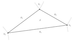
A triangle can be divided into three separate regions, a face region (F), three edge regions (E1, E2, E3) and three vertex regions (V1, V2, V3).
float3 ClosetPointToTriangle(int indexA, int indexB, int indexC, float3 P, out int2 feature)
{
    float3 A = MeshVerticesBuffer[indexA].xyz;
    float3 B = MeshVerticesBuffer[indexB].xyz;
    float3 C = MeshVerticesBuffer[indexC].xyz;

    float snom = dot(P - A, B - A);
    float sdenom = dot(P - B, A - B);

    float tnom = dot(P - A, C - A);
    float tdenom = dot(P - C, A - C);

    if (snom <= 0.0 && tnom <= 0.0)
    {
        feature = int2(indexA, indexA);
        return A;
    }

    float unom = dot(P - B, C - B);
    float udenom = dot(P - C, B - C);

    if (sdenom <= 0.0 && unom <= 0.0)
    {
        feature = int2(indexB, indexB);
        return B;
    }

    if (tdenom <= 0.0 && udenom <= 0.0)
    {
        feature = int2(indexC, indexC);
        return C;
    }

    // compute the normal
    float3 n = cross(B - A, C - A);

    // for AB check triple scalar product [N PA PB]
    float coordsPAB = dot(n, cross(A - P, B - P));
    if (coordsPAB <= 0 && snom >= 0.0 && sdenom >= 0.0)
    {
        feature = int2(indexA, indexB);
        return A + snom / (snom + sdenom) * (B - A);
    }

    // for BC check triple scalar product [N PB PC]
    float coordsPBC = dot(n, cross(B - P, C - P));
    if (coordsPBC <= 0 && unom >= 0.0 && udenom >= 0.0)
    {
        feature = int2(indexB, indexC);
        return B + unom / (unom + udenom) * (C - B);
    }

    // for CA check triple scalar product [N PC PA]
    float coordsPCA = dot(n, cross(C - P, A - P));
    if (coordsPCA <= 0 && tnom >= 0.0 && tdenom >= 0.0)
    {
        feature = int2(indexA, indexC);
        return A + tnom / (tnom + tdenom) * (C - A);
    }

    // P is inside triangle
    // normalize barycentric coordinates
    float u = coordsPBC / (coordsPAB + coordsPBC + coordsPCA);
    float v = coordsPCA / (coordsPAB + coordsPBC + coordsPCA);
    float w = 1.0 - u - v;
    feature = int2(-1, -1);
    return u * A + v * B + w * C;
}
One additional change I implement in the algorithm is to return the Voronoi feature that we are closest to. For example, if we are closest to one of the triangle’s vertices we are going to return the closest vertex, if we are closest to one of the edges the function returns the two vertices that make up that edge. Finally, if the closest point is inside the triangle we return -1. Knowing the closest Vornoi feature will be helpful when computing the sign of the distance, a.k.a. determining if we are inside or outside the mesh.
Next, we will add an inline function that computes the average normal from a triangle’s vertices:
inline float3 GetTriangleNormal(int indexA, int indexB, int indexC)
{
    float3 A = MeshVerticesBuffer[indexA].xyz;
    float3 B = MeshVerticesBuffer[indexB].xyz;
    float3 C = MeshVerticesBuffer[indexC].xyz;
    return normalize(cross(B - A, C - A));
}
Now, let’s create the thread kernel. As mentioned earlier the thread kernel group will have 8x8x8 threads:
[numthreads(8,8,8)]
void CSMain (uint3 dispatchID : SV_DispatchThreadID)
{

}
The dispatchID variable is provided automatically with the voxel ID. We can divide the process of generating the SDF into two main parts: one is finding the closest distance and the second part is determining whether the voxel is inside or outside the mesh and set the sign of the distance accordingly. Let’s start with the first part where we set up a few variables and iterate over all triangles, find the closest point on the triangle and compute the distance. If the distance is the smallest one so far, we are going to store it along with some other thing we are going to need when computing the sign such as normal, direction, and the Voronoi feature.
// get triangle count
uint meshTriangleCount, dummy;
MeshTrianglesBuffer.GetDimensions(meshTriangleCount, dummy);

// get the local space postition
float3 currentGridPoint = CoordToPosition(dispatchID.xyz);

int indexA, indexB, indexC;
float minimumDistance = 1000000.0;
int2 minimumFeature;
float3 minimumNormal;
float3 minimumDirection;

// iterate over all triangles
for (uint i = 0; i < meshTriangleCount; i += 3)
{
    indexA = MeshTrianglesBuffer[i + 0];
    indexB = MeshTrianglesBuffer[i + 1];
    indexC = MeshTrianglesBuffer[i + 2];

    int2 currentFeature;
    float3 closestPoint = ClosetPointToTriangle(indexA, indexB, indexC, currentGridPoint, currentFeature);
    float3 currentDirection = currentGridPoint - closestPoint;
    float3 currentNormal = GetTriangleNormal(indexA, indexB, indexC);
    float currentDistance = distance(currentGridPoint, closestPoint);

    if (currentDistance < minimumDistance)
    {
        minimumDistance = currentDistance;
        minimumFeature = currentFeature;
        minimumDirection = currentDirection;
        minimumNormal = currentNormal;
    }
}
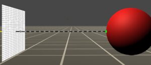
A signed distance field must also store the sign of the distance. When computing the distance from a cell to the triangle if the cell is inside the mesh the distance should be negative otherwise positive. The problem of finding if a point lies outside or inside of a mesh does not has a trivial solution. This can also have inconsistent results for very thin meshes. My first attempt at determining the sign was performing a dot product operation between the normal of the closest triangle and the vector determined by the initial and the closest point. This is only accurate in certain scenarios. Let’s assume that the closest feature is a vertex and the vertex is shared by two triangles. The problem appears if those two triangles return different signs and since both qualify as the closest triangle the signed returned depends only on the ordering of the triangles in the memory:
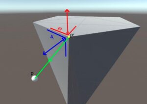
Consider the initial point being the white sphere (P) and the yellow projected point (P’). Both triangles A and B contain the point P’ so both can be considered the closest to P. However, A and B have different normals, therefore, returning different signs.
The second attempt was to compute the average normal of all the triangles that share the same edge or vertex. With the improved algorithm, an average normal would be determined from triangles A, B, and any other triangle that shares vertex P’. While this is not 100% accurate it provides accurate results in all tested scenarios.
With that being said, the final step is to implement this algorithm to find the sign and assign the final distance value to the output compute buffer. Note how the final distance is normalized to a [0, 1] range in order to to be able to visualize the SDF at any scale later on.
// ========= let's find the sign ============
float finalDistance;
if (minimumFeature.x == -1 && minimumFeature.y == -1)
{
    finalDistance = minimumDistance * sign(dot(minimumDirection, minimumNormal));
}
else
{
    float3 normal;
    float3 averageNormal = float3(0, 0, 0);
    float3 feature1 = MeshVerticesBuffer[minimumFeature.x];
    float3 feature2 = MeshVerticesBuffer[minimumFeature.y];

    for (uint j = 0; j < meshTriangleCount; j += 3)
    {
        int b = 0;
        for (uint k = j; k < j + 3; k++)
        {
            float3 inspectedPos = MeshVerticesBuffer[MeshTrianglesBuffer[k]];
            if (distance(inspectedPos, feature1) < 0.001)
            {
                b++;
            }
            if (distance(inspectedPos, feature2) < 0.001)
            {
                b++;
            }
        }

        // if the closest point is shared by 2 or more triangles we need to compute the average normal
        if (b >= 2)
        {
            normal = MeshNormalsBuffer[MeshTrianglesBuffer[j + 0]] + MeshNormalsBuffer[MeshTrianglesBuffer[j + 1]] + MeshNormalsBuffer[MeshTrianglesBuffer[j + 2]];
            averageNormal += normal;
        }
    }

    finalDistance = minimumDistance * sign(dot(minimumDirection, averageNormal));
}

float sdfScale = (MaxExtents.x - MinExtents.x);
Output[CoordsToBufferIndex(dispatchID.x, dispatchID.y, dispatchID.z)] = finalDistance / sdfScale;
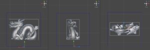
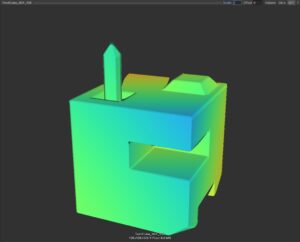
And we are done! Now go back to the editor, drag and drop a mesh (or pick one of Unity’s default ones) into the mesh field of the SdfGenerator window, click bake and then go in the project panel and check the 3D texture created. You can click on the SDF tab on the top right corner of the preview window in order to visualize the SDF. If it looks too “inflated” or it is not shown completely, play with the scale value. Unity’s built-in SDF visualizer is not great, so in the next section, we will focus on building a sphere-marching visualizer so we can properly inspect our SDFs.
And with this, I end the first section of this tutorial series. We now have a working SDF generator which provides a strong basis for all the things we are going to do with it in the future. I apologize for the long post and I promise the next sections won’t be as long as this one.
Don’t forget to check the GitHub repo here, and leave a comment below.
Stay safe!
Hi Matei, thanks a lot for your effort on this SDF series, and I followed the first part which also works well on low resolution with the Chinese dragon model. But when I switch the resolution from 16 to 32, unity throwed out warning “failed to present d3d11 swapchain due to device reset/removed. this error can happen if you draw or dispatch very expensive workloads to the gpu”, then close the program. The GPU I have is GTX1070 and I tried to update the driver and update unity to 2020.2.2, but it didn’t help at all. Dose it mean I have to buy a better GPU? Looking forward your reply~
Hi Alex, this error is most of the time linked to a feature of Windows called TDR (Timeout Detection & Recovery). Basically, if the GPU doesn’t “respond” after a number of seconds the OS resets it, which crashes our program. I believe the default timeout is 2 seconds. In order to increase the timeout value please follow this: https://docs.substance3d.com/spdoc/gpu-drivers-crash-with-long-computations-128745489.html(I set mine to 60 seconds). Thank you for pointing this out. I will update the post with this info in case other users encounter this problem.
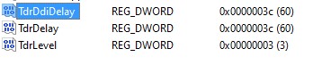
This is how I configured this:
YES! It works well now! Thank you sooooo much! Do you have patreon or other way that I can buy you a coffee~
I am very glad it worked! I really appreciate it but at the moment I don’t have a Patreon. I plan to do something like that in the future once I have a more consistent roadmap of tutorials. However, I have a PayPal.me profile: paypal.me/MateiGiurgiu
incredible valuable! so thanks a lot for this.
i added support for unevenly sized 3d textures (like 32x64x32) and now it firs just perfectly.
Hey, I am glad you found it useful and good job for adding support for non-uniform 3d textures.